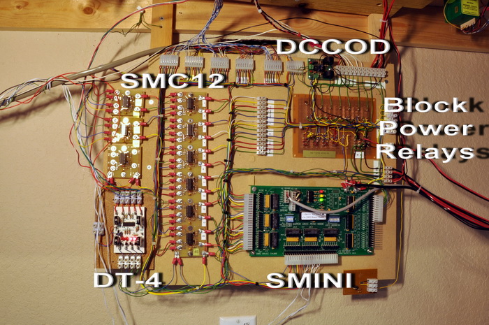
One of the five SMINI boards, along with its various support components is shown here. Each SMINI card has 48 output and 24 input lines. It also has a serial port (RS-485) which provides a connection the railroad PC. The PC communicates with the SMINI card using a simple and straightforward protocol. The input lines can be thought of as sensing whether or not they are connected to ground or open. Thus a simple push button switch connected to ground and an input line can trigger a SMINI input. Similarly the output lines can be thought of as simple off-on switches that can connect a device to ground. An example would be a light bulb connected to say a five volt supply on one side and an output line on the other.
The software running in the PC can query the SMINI cards as to the state of its input lines and thus can tell if, for example, a button is pushed, or an occupancy detector senses a train. The software running in the PC can also send information that sets the state of each output line. For example, the PC can tell the SMINI to turn on a signal light or throw a turnout by setting an output line's state.
The SMINI cards are part of a complete model railroad control system developed by Bruce Chubb at JLC Enterprises. My SMINI cards were built from kits supplied by Don Woods at Easee Interfaces.
Click on the photo to enlarge it.